Basic composition
Inner and outer rings: precision machined tracks with grooves, usually made of high carbon chromium steel.
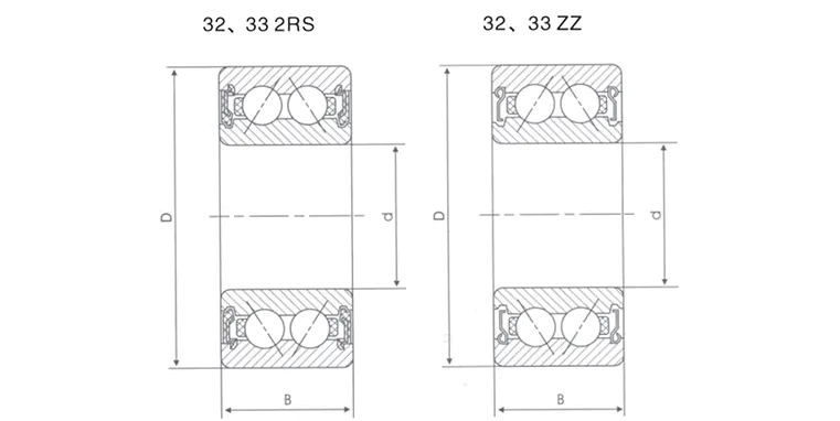
Double row balls: two rows of steel balls are arranged at a specific angle to achieve bidirectional load sharing.
Cage: nylon, brass or steel, to ensure uniform distribution of balls and reduce friction.
Contact angle (α): usually 15°, 25° or 40°, the larger the angle, the stronger the axial load capacity.
Differences from single row bearings
|
Features
|
Single row angular contact ball bearing
|
Double row angular contact ball bearing
|
|
Load direction
|
One-way axial + radial
|
Two-way axial + radial
|
|
Rigidity
|
Lower
|
Higher (double row support)
|
|
Installation complexity
|
Need to be used in pairs
|
Use independently to simplify assembly
|
2. Principle of high load-bearing capacity
- Mechanical advantages of double-row symmetrical layout
Radial load: Two rows of balls share radial force and reduce single-point stress concentration.
Axial load: The contact angle design decomposes the axial force into radial force, and the double-row structure can offset the thrust in both directions.
Torque load: The ability to resist overturning moment is significantly better than that of single-row bearings.
- Influence of key design parameters
Contact angle (α):
α=15°: Focus on radial load (such as pump equipment).
α=25°~40°: Focus on axial load (such as machine tool spindle).
Preload adjustment: Eliminate clearance by preload, improve rigidity but balance the risk of temperature rise.
- Material and process enhancement
Steel ball material: Ceramic ball (Si3N4) can reduce weight and withstand high temperature.
Groove polishing: Nano-scale surface treatment reduces friction loss.
3. Typical application scenarios
Machine tool spindle: High rigidity requirements under bidirectional cutting force.
Industrial robot joints: bear dynamic loads in multiple directions.
- Heavy load and high speed compatible scenarios
Gearbox: transmit radial force and axial thrust at the same time.
Centrifugal compressor: stability requirements under high-speed rotation.
4. Selection and use recommendations
Selection points
Load type: The axial/radial ratio determines the contact angle selection.
Speed limit: refer to the limit speed (dn value) in the bearing manual.
Lubrication method: grease lubrication (easy maintenance) or oil lubrication (high-speed scenario).
Common misunderstandings
Wrong preload: over-tightening causes temperature rise, and over-loosening causes vibration.
Mixed pairing: avoid mixing with single-row bearings to cause uneven force.
Maintenance key
Regularly check the clearance: the preload force may fail after wear.
Lubrication cycle: the grease change interval needs to be shortened in high temperature environment.
 English
 中文简体
中文简体 Deutsch
 Español


