A double row angular contact bearing is a rolling element bearing that contains two rows of balls arranged side by side within a single outer ring, both rows making contact with their raceways at a defined contact angle—typically 25° or 30°—rather than at 90° to the bearing axis. This angular contact geometry allows the bearing to simultaneously carry radial loads (perpendicular to the shaft) and axial loads (along the shaft axis) in both directions, while the double-row arrangement provides significantly higher load capacity and greater rigidity against tilting moments than a single-row angular contact bearing of the same outer diameter.
In practical engineering terms, a double row angular contact bearing replaces what would otherwise require two separate single-row angular contact bearings mounted face-to-face or back-to-back, doing so in a narrower axial space and without the need for matched preloading during assembly. This makes it a highly efficient bearing solution for applications that combine heavy combined loads with space constraints—most notably machine tool spindles, automotive wheel hubs, gearboxes, and pumps.
The Principle of Angular Contact: Why the Contact Angle Matters
The defining feature of any angular contact bearing—single or double row—is the contact angle: the angle between the line connecting the points of contact of the ball with the inner and outer raceways, and a plane perpendicular to the bearing axis. In a deep groove ball bearing, this angle is effectively zero under no-load conditions; in an angular contact bearing, it is a designed, fixed geometry.
How Contact Angle Affects Load Capacity
The contact angle determines the ratio of axial to radial load capacity. A larger contact angle increases axial load capacity relative to radial capacity; a smaller contact angle does the opposite. The relationship is approximately linear within the practical range of contact angles used in commercial bearings:
- 15° contact angle — relatively high radial capacity, moderate axial capacity; used where radial loads dominate and some axial load support is needed
- 25° contact angle — balanced radial and axial capacity; the most common angle in double row angular contact bearings for general machine tool and pump applications
- 30° contact angle — higher axial capacity; used in applications with significant sustained axial forces, such as some gearbox and compressor arrangements
- 40° or 45° contact angle — very high axial capacity; found in specialized thrust-dominant applications; less common in double row configuration
The Effect of Induced Axial Load
A single-row angular contact bearing loaded radially generates an internal axial force component as a consequence of its contact angle—this is the induced axial load. When two single-row angular contact bearings are paired, they are arranged so that their induced axial loads oppose each other and cancel. In a double row angular contact bearing, this balance is achieved internally within the single bearing unit because the two rows have their contact angles opposed: one row carries axial force in one direction, the other row carries axial force in the opposite direction. The result is a bearing that is inherently balanced for bidirectional axial load without any special mounting arrangement.
Structure and Internal Geometry of a Double Row Angular Contact Bearing
Understanding the internal construction of a double row angular contact bearing explains both its performance advantages and its specific operational requirements.
Outer Ring
The outer ring is a single-piece component with two raceway grooves machined to the precise curvature required for the specified ball size and contact angle. The one-piece construction ensures perfect concentricity between the two raceways and provides the structural rigidity that gives the double row bearing its tilting moment resistance—a capability absent from paired single-row arrangements where the two rings are independent components.
Inner Ring: One Piece or Split
The inner ring of a double row angular contact bearing may be either a single piece or a split (two-piece) construction. A single-piece inner ring provides maximum rigidity and is used in the majority of standard double row designs. A split inner ring—in which the inner ring consists of two halves that can be separated—allows larger ball complements to be assembled, increasing load capacity; however, the split joint introduces a potential source of stress concentration and limits the maximum speed at which the bearing can operate reliably.
Ball Complement and Cage
Each row of a double row angular contact bearing contains a full complement of balls—the maximum number of balls that can be accommodated while maintaining the necessary minimum separation between adjacent balls. The cage (retainer) maintains uniform ball spacing within each row, prevents ball-to-ball contact, and guides the balls through the unloaded zone as the bearing rotates. Cages for double row angular contact bearings are typically made from pressed steel, polyamide (nylon), or machined brass, depending on the operating speed, temperature, and lubrication conditions.
Preload
Double row angular contact bearings are manufactured with a defined internal preload—a pre-compression applied to the balls between the inner and outer ring raceways during manufacture, before any external load is applied. This preload eliminates internal clearance, increases bearing stiffness, and significantly improves running accuracy. Preload is specified as light (C), medium (CA), or heavy (CB) and is a critical parameter for machine tool spindle applications where sub-micrometre runout accuracy is required. A bearing with excessive preload will overheat and fail prematurely; insufficient preload produces vibration and reduced accuracy under load.
Performance Characteristics: Load Capacity, Stiffness, and Speed
The performance characteristics of double row angular contact bearings are determined by their geometry, dimensions, and the material and quality of their components. The following quantitative relationships are central to understanding when and why to specify this bearing type.
Dynamic and Static Load Capacity
The dynamic load rating (C) of a double row angular contact bearing—the load at which the bearing has a theoretical rating life of one million revolutions—is approximately 1.6 to 1.8 times the dynamic load rating of a comparable single-row angular contact bearing of the same bore diameter and series. This increase reflects the additional ball row sharing the applied load. The static load rating (C₀), which defines the maximum load at which the bearing can sustain without causing permanent deformation of the raceways or balls, shows a similar proportional increase over single-row equivalents.
Stiffness and Tilting Moment Capacity
Bearing stiffness—resistance to elastic deflection under load—is a critical parameter in machine tool spindles, where deflection directly translates to dimensional error in the machined workpiece. The one-piece outer ring of a double row angular contact bearing provides a fixed, known distance between the two rows' contact points, creating a stable moment arm that resists shaft tilting under overhanging tool loads or eccentric workpiece forces. This tilting moment resistance is one of the primary reasons double row angular contact bearings are the standard choice in machine tool spindles for both manual and CNC turning, milling, and grinding equipment.
Speed Limits
The maximum operating speed of a double row angular contact bearing is lower than that of a comparable single-row angular contact bearing, due to the greater heat generation from two rows of rolling elements and the higher internal stresses associated with preloaded operation. Bearing catalogues typically specify two speed limits:
- Thermal speed limit — the speed at which heat generation and dissipation reach equilibrium under reference lubrication conditions; exceeding this limit causes progressive temperature rise that degrades lubricant and accelerates bearing wear
- Mechanical speed limit — the speed at which cage and ball centrifugal forces reach the structural limits of the cage material; typically higher than the thermal limit for most greased bearings
For a typical double row angular contact bearing of 70 mm bore diameter, speed limits in the range of 5,000 to 12,000 rpm are common depending on series, cage material, lubrication method, and preload level. Oil mist or jet lubrication extends achievable speeds beyond the grease-lubricated thermal limit.
Double Row Angular Contact Bearings vs. Alternative Bearing Arrangements
To understand where double row angular contact bearings are most appropriate, comparing them to the most common alternatives clarifies their specific advantages and limitations.
Comparison of double row angular contact bearings with equivalent bearing arrangements across key performance criteria
| Criterion |
Double Row Angular Contact |
Paired Single-Row Angular Contact |
Deep Groove Ball Bearing |
Tapered Roller Bearing (Pair) |
| Radial load capacity |
High |
High |
Moderate |
Very High |
| Bidirectional axial capacity |
High |
High |
Low–Moderate |
High |
| Tilting moment resistance |
Very Good |
Good (depends on spacing) |
Poor |
Good |
| Axial space required |
Compact |
Wider (two separate bearings) |
Narrow |
Wide |
| Maximum speed capability |
Moderate–High |
High |
Very High |
Moderate |
| Running accuracy |
Very High (precision classes available) |
High (matched pair required) |
Moderate |
Moderate |
| Assembly simplicity |
Simple (single unit, pre-preloaded) |
Complex (preload requires matched pair) |
Simple |
Moderate (preload adjustment needed) |
Primary Applications of Double Row Angular Contact Bearings
The specific combination of properties offered by double row angular contact bearings makes them the engineered optimum for several demanding applications where alternatives are either inadequate or less efficient.
Machine Tool Spindles
Machine tool spindles—in lathes, milling machines, grinding machines, and machining centres—require bearings that are simultaneously very stiff, very accurate, capable of carrying the combined radial and axial cutting forces, and compact enough to fit within the spindle cartridge. Double row angular contact bearings, specified in ISO precision classes P5, P4, or P2 (equivalent to ABEC 5, 7, or 9), achieve radial runout values as low as 1 to 3 micrometres in the highest precision classes, enabling surface finishes and dimensional tolerances in machined workpieces that are impossible with lower-accuracy bearing arrangements.
Automotive Wheel Hubs
Modern automotive non-driven front wheel hub assemblies (and in some designs, rear wheel assemblies) use double row angular contact bearings as the central load-carrying element. The vehicle weight acts as a large radial load, cornering forces add a bidirectional axial component, and braking and acceleration create tilting moments at the wheel hub—a combination that makes the double row angular contact bearing the natural choice. Automotive-specification wheel hub bearings are typically sealed-for-life units with integrated flanges for wheel and brake disc attachment, requiring no field lubrication adjustment throughout their service life of typically 150,000 to 250,000 km.
Pumps, Compressors, and Fans
Centrifugal pumps and fans generate significant radial loads from the impeller weight and hydraulic/aerodynamic forces, combined with axial loads from pressure differences and belt or coupling misalignment. Double row angular contact bearings in the bearing housings of these machines handle these combined loads efficiently while providing the running accuracy necessary for reliable shaft sealing—a critical requirement since shaft seal failures are the primary cause of pump downtime in most plant maintenance records.
Gearboxes and Reducers
In bevel gear and helical gear stages, the gear geometry generates both radial and axial forces on the shaft simultaneously. A single double row angular contact bearing can carry these combined loads at the gear shaft, replacing what would otherwise require two single-row bearings in a span arrangement. This simplifies the gearbox housing design, reduces parts count, and decreases assembly time—all of which contribute to reduced manufacturing cost for the gearbox designer.
Robotics and Precision Rotary Joints
Industrial robot joints and precision rotary positioning stages require bearings with very high stiffness, low runout, and the ability to carry moment loads from the cantilevered arm and payload. Slim-section double row angular contact bearings—characterised by a very thin cross-section relative to bore diameter—are used in robot joints where every millimetre of axial space is critical and the bearing must provide the full load capacity of a conventional deep section bearing within a fraction of the axial width.
Designation and Specification: Reading Bearing Codes
Double row angular contact bearings are identified by standardised designation codes that encode the bearing's key parameters. Understanding these codes allows engineers to specify, source, and cross-reference bearings from different manufacturers.
A typical double row angular contact bearing designation follows this structure:
- Type designation — the prefix or lead number identifying the bearing as a double row angular contact type (e.g., 32, 33, 52, 53 in ISO/DIN designation systems, where 52 and 53 indicate double row angular contact bearings with a one-piece inner ring)
- Bore code — two digits indicating the bore diameter (e.g., 08 = 40 mm, 10 = 50 mm, 12 = 60 mm in the 5× system for bore codes 04 and above)
- Width series — a digit indicating the axial width relative to bore diameter
- Suffix codes — letters indicating contact angle (A = 30°), preload level (C, CA, CB), precision class (P5, P4, P2), sealing (RS, 2RS), and cage type (M = brass, TN = polyamide)
For example, a bearing designated 3206 A-2RS is a double row angular contact bearing with 30 mm bore, 30° contact angle, and two-sided rubber seals for grease retention and contaminant exclusion in sealed-for-life applications.
Lubrication, Sealing, and Maintenance Considerations
Correct lubrication is essential for achieving the rated life of any rolling element bearing, and double row angular contact bearings present specific requirements that differ from simpler bearing types.
Grease Lubrication for Standard Applications
The majority of double row angular contact bearings in general industrial applications are grease-lubricated. The bearing cavity is filled with grease during assembly to approximately 30 to 50% of the free space volume—overfilling generates heat from churning and can cause premature bearing failure. For bearings operating at moderate speeds and temperatures, a high-quality lithium-complex grease with a consistency of NLGI 2 and a temperature range of -30°C to +120°C is appropriate. For higher speed operation, lower-viscosity, low-churning-loss greases are specified.
Oil Lubrication for High-Speed Machine Tool Applications
In machine tool spindles operating near or at the bearing's speed limit, oil mist lubrication, oil-air lubrication, or oil jet lubrication may be used instead of grease. These methods provide continuous lubricant replenishment and active cooling of the bearing, allowing operation at speeds 20 to 50% higher than the grease-lubricated thermal speed limit. The lubricant viscosity is selected based on the bearing's operating speed parameter (n·dm, where n is speed in rpm and dm is the mean bearing diameter in mm), with lower viscosity oils used at higher speed parameters.
Sealed vs. Open Bearings
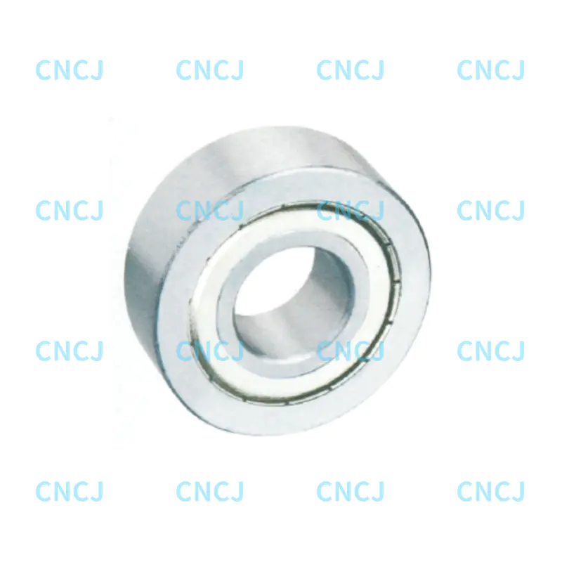
Double row angular contact bearings are available in open (unshielded), shielded (metal shields, 2Z designation), and sealed (rubber seals, 2RS designation) configurations. Sealed bearings are pre-filled with grease for life and require no re-lubrication—they are the standard choice for automotive wheel hubs and for industrial applications in contaminated environments where bearing replacement is more practical than periodic lubrication. Open bearings are used in machine tool spindles and other precision applications where the lubrication system is part of the machine design and contamination is controlled by other means (labyrinth seals, positive air pressure).
 English
 中文简体
中文简体 Deutsch
 Español


