An inspector mics a 30 mm shaft at 30.018 mm. The drawing calls for 30 mm nominal, and the question on the bench is whether the part ships or goes in the reject bin. A metric tolerance table answers that in seconds, but only when three inputs are fed to it in the right order: the nominal size band, the fundamental deviation letter, and the tolerance grade. Get one of those wrong and a perfectly usable shaft is scrapped while a genuinely loose joint still reaches assembly. The table is not complicated. The reading of it is where things go wrong.
The short answer first. Every value in a metric tolerance table is a band width in microns, not a plus or minus figure in millimetres. A 30 mm IT7 bore is allowed 21 microns of size variation, which is 0.021 mm. Treating that 21 as millimetres, or halving it into plus or minus 10.5 microns, are the two mistakes we see most often on incoming inspection reports.
The Three Inputs Behind Every Metric Tolerance Table
ISO 286 defines the system. Part 1 sets out the tolerance grades, and Part 2 lists the limit deviations for shafts and holes up to 3150 mm. ANSI B4.1 covers the inch equivalent using thousandths of an inch, so a drawing that quotes both systems in the same note will not agree with itself. Choose one and stay with it through the whole tolerance chain.
Nominal size is the first input. Tolerance values step in bands, and the band boundaries matter more than most people expect. A 30 mm feature belongs to the over 18 up to 30 mm range, while a 30.5 mm feature has already moved into the over 30 up to 50 mm range, where the permitted variation is wider.
The letter is the second input. Lowercase letters describe shafts, uppercase letters describe holes. The letter fixes where the tolerance zone sits relative to the zero line, which is the nominal size itself, and that position decides whether the joint clears or grips.
The grade is the third input. IT grades run from IT1 to IT18, and the higher the number, the wider the band.
ISO 286 fundamental tolerances in microns for common IT grades. The same values apply to shafts and holes within the same nominal band, so only the deviation letter decides whether a joint clears or grips.
| Nominal diameter (mm) |
IT5 |
IT6 |
IT7 |
IT8 |
IT9 |
IT10 |
IT11 |
| Over 3 to 6 |
5 |
8 |
12 |
18 |
30 |
48 |
75 |
| Over 6 to 10 |
6 |
9 |
15 |
22 |
36 |
58 |
90 |
| Over 10 to 18 |
8 |
11 |
18 |
27 |
43 |
70 |
110 |
| Over 18 to 30 |
9 |
13 |
21 |
33 |
52 |
84 |
130 |
| Over 30 to 50 |
11 |
16 |
25 |
39 |
62 |
100 |
160 |
| Over 50 to 80 |
13 |
19 |
30 |
46 |
74 |
120 |
190 |
| Over 80 to 120 |
15 |
22 |
35 |
54 |
87 |
140 |
220 |
Now read a real case. A 30 mm bore to H7 sits in the over 18 up to 30 mm band. H is a hole with its lower deviation at zero, so the bore may measure anywhere from 30.000 to 30.021 mm. A mating shaft to k6 in the same band runs from 30.002 to 30.015 mm. The joint is a transition fit with up to 19 microns of clearance or 15 microns of interference, and that is the complete story of the pair.
IT Grades: What Each Step Actually Buys
Each step in the grade series is roughly 1.6 times wider than the one above it, which means precision gets expensive quickly. On a 50 mm bore, IT8 allows 39 microns and generally comes off a lathe or a decent machining centre. IT6 allows 16 microns and normally means grinding, often with a fixture and an extra inspection pass.
Matching the grade to the job keeps cost under control. IT5 and IT6 belong on gauge masters, spindle journals and precision bearing seats. IT7 covers most bearing housings, gearbox bores and hydraulic bores. IT8 suits press fits that only need to stay tight, and IT9 to IT11 are acceptable for locating features that never carry load.
One check that prevents arguments later: add the two component tolerances to the measurement uncertainty and compare that total with the clearance window the joint actually needs. If the sum is larger than the window, no inspection plan will rescue the design.
Shaft and Hole Fits: Reading the Letters Correctly
Shaft deviations from a to g sit below the zero line, so they always clear the matching hole. The letter h puts the upper deviation at zero, so the shaft is never larger than nominal. The letters j and k and m and n form transition zones, and p through zc sit above the zero line as interference. Holes follow the same logic in uppercase, and the pattern mirrors: A to G clear, H sits at or above nominal, J to N transition, P to ZC interference.
Hole basis, written with a capital H, is the default in most machine design because a reamed or bored hole is easier to hold and a shaft can be ground to suit it. Shaft basis, with a lowercase h, appears when finished shaft stock or a purchased shaft has to mate with several different bores.
Clearance and interference ranges for a 30 mm nominal joint, calculated from ISO 286 limit deviations. Negative values are interference, positive values are clearance.
| Fit |
Type |
Range at 30 mm (microns) |
Typical use |
| H7/g6 |
Sliding |
7 to 41 clearance |
Locating rings and guides that need axial float |
| H7/h6 |
Locational clearance |
0 to 34 clearance |
Joints that must come apart by hand |
| H7/k6 |
Transition |
19 clearance to 15 interference |
Bearing seats under light load, dowel location |
| H7/n6 |
Transition |
6 clearance to 28 interference |
Semi-permanent joints, light press fit |
| H7/p6 |
Interference |
1 to 35 interference |
Bearing inner rings under normal to heavy load |
| H7/s6 |
Forced |
14 to 48 interference |
Heavy shock loads, needs heating or a press |
From Table to Bearing Seat
The rule that decides most bearing fits is load direction. If the load rotates relative to the inner ring, the inner ring needs interference on the shaft and the outer ring should sit with a small clearance in the housing. If the outer ring carries the rotating load, as in a wheel hub, the numbers swap and the housing gets the interference.
In practice, a shaft in k5 or k6 covers normal loads, while m5 or m6 suits heavier duty. A stationary outer ring usually runs in an H7 or J7 housing. Once the outer ring rotates, K7 or M7 becomes the safer starting point, and the bore is often finished by grinding after the housing is assembled to keep roundness in check. Model selection deserves the same care as the fit itself, and this guide on bearing model selection walks through the load and speed questions that come before the tolerance call.
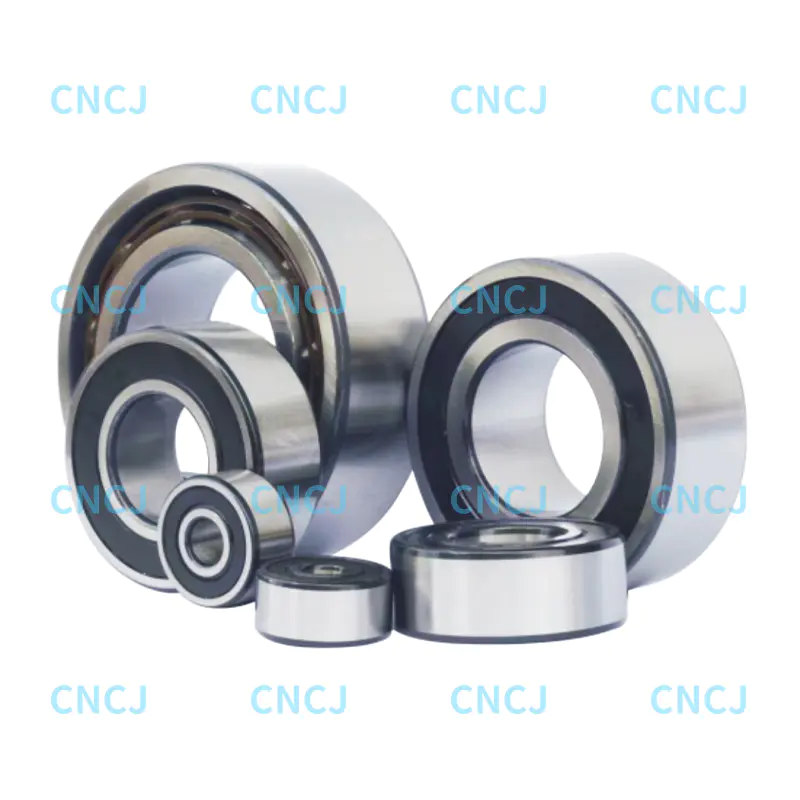 32 and 33 Series Double Row Angular Contact Ball BearingsAfter shaft and housing fit guidance, these double-row angular contact bearings suit combined radial and axial loads; the 32 series offers larger axial capacity.View Product →
Housing material changes the answer too. Aluminium expands at roughly 23 microns per metre per degree Celsius against 11 to 12 for steel, so an aluminium housing that is correct on the bench can lose its grip at operating temperature. In those applications the initial fit has to be tighter, or the housing needs a steel insert.
Fit, Clearance and Preload: What the Table Does Not Show
An interference fit steals part of the bearing internal clearance. As a working rule, roughly 70 to 80 percent of the diametral interference converts into reduced radial internal clearance, and the share rises on thin-walled rings and hollow shafts. A k6 seat on a 30 mm bore can therefore consume 10 to 12 microns of clearance before the machine ever runs.
ISO 5753 groups such as CN and C3 exist precisely for this reason. The clearance group should be chosen after the fit is calculated, not before, because a bearing that starts at the low end of CN and loses 11 microns to the fit may end up preloaded and running hot. Preloaded arrangements deserve a verification step as well, usually a torque check on the assembled shaft or a temperature rise measurement during a short run-in.
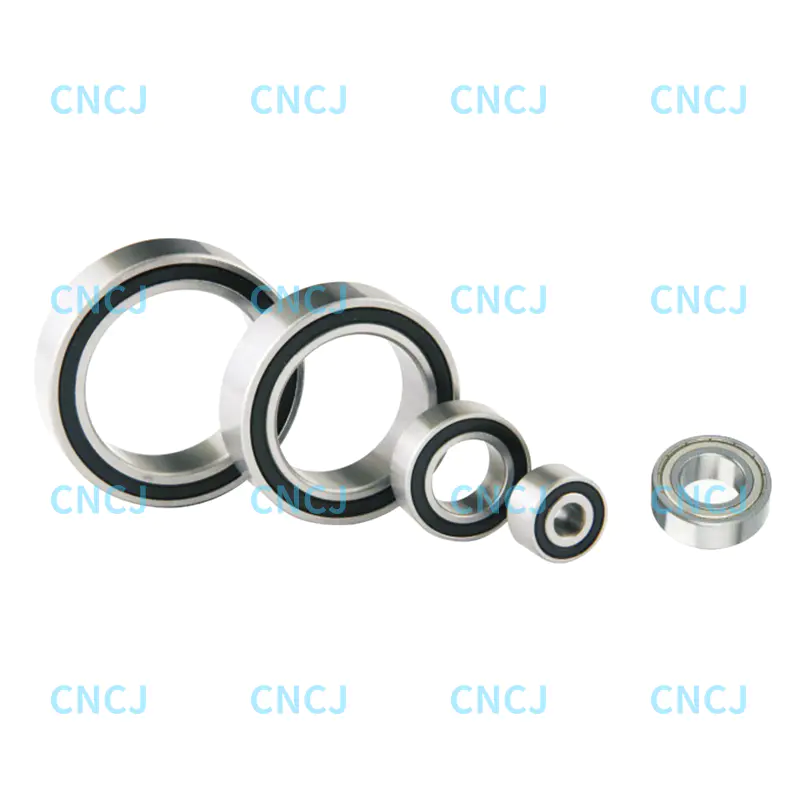 52 and 53 Series Double Row Angular Contact Ball BearingsWhen clearance groups and running noise matter, these double-row angular contact bearings offer sealing and lubrication options for spindles, wind power, wheel hubs, and pumps.View Product →
Where the assembly is expected to run at speed, the fit also affects noise. A seat that is too loose lets the ring creep, and creep shows up as a low frequency rumble long before any visible wear appears.
Where the Table Stops and the Part Begins
Temperature is the first blind spot. Steel grows about 11.5 microns per metre for every degree Celsius. A 100 mm steel bore measured at 30 degrees Celsius instead of the 20 degree reference is roughly 11.5 microns larger than its certified size, and in the over 80 to 120 mm band an IT7 tolerance is only 35 microns wide, so that drift alone eats a third of the allowance.
Measurement uncertainty is the second. A good hand micrometer holds plus or minus 2 microns on a controlled part with a skilled operator, and once gauge calibration, part temperature and technique are added, 4 to 6 microns is a realistic figure. That number has to sit inside the tolerance band, not beside it.
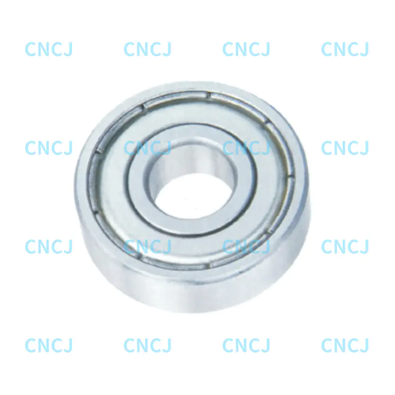
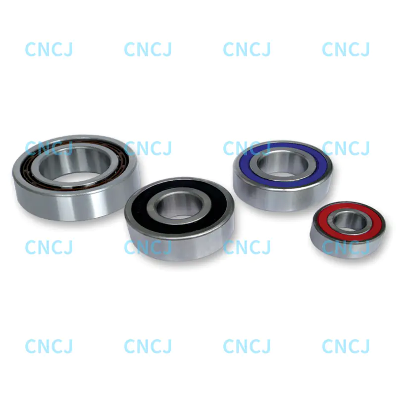 Deep Groove Ball Bearings from Ningbo Wanshun BearingFor checking roundness, surface finish, and press-fit conditions, this deep groove ball bearing product provides inquiry and quote access.View Product →
Geometry is the third. Size tables say nothing about roundness, cylindricity, taper or surface finish. A three-lobed bore can pass a two-point micrometer check and still produce a fit that rattles or seizes. Press fits generally want a surface finish below about 0.4 microns Ra, because a rougher surface shears during assembly and quietly gives back part of the interference you calculated.
A Practical Check Before You Approve a Fit
- Confirm the nominal band, the standard and the unit system on both drawings before comparing any numbers.
- Convert the table value from microns to millimetres and write the actual limits on the drawing, not just the class code.
- Identify whether the load rotates with the inner ring or the outer ring, and check that the interference is on the loaded ring.
- Subtract the expected clearance loss from the required internal clearance, then confirm the clearance group still fits the application.
- Soak the part to the reference temperature and verify the measuring equipment, including calibration, before accepting or rejecting.
- Inspect form and finish separately. Size alone does not describe a fit.
None of this makes the metric tolerance table unreliable. It simply means the table gives you the size band, and everything else about the joint comes from load direction, temperature, clearance loss and geometry. We build high precision, low noise double row angular contact ball bearings and deep groove bearings against these same ISO 286 rules, and the tolerance chain is checked again at assembly rather than only on the drawing board. When a fit is critical, build one joint, measure the assembly force, and let the part confirm what the table predicted.
 English
 中文简体
中文简体 Deutsch
 Español