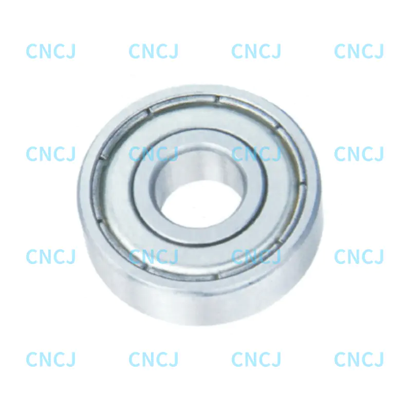
An H7 hole and a p6 shaft at a 25 mm nominal size give you between 1 and 35 microns of interference. That single number, not the letter pair written on the drawing, decides whether a gear hub holds under torque or starts spinning on the shaft after the first warm-up cycle. A press fit tolerance chart exists to help you find that number quickly and reliably.
The conclusion first: read the chart for the interference range, then test that range against load, material and working temperature. Charts rarely fail on their own. Fits fail when someone copies an H7/p6 note from an old drawing and applies it to a thin-walled aluminium housing running at 90 C.
What a Press Fit Tolerance Chart Actually Contains
A standard chart, whether it follows ISO 286 or the older ANSI B4.2 system, is built from four pieces of data:
- Nominal size band, such as 18 to 30 mm or 30 to 50 mm. Limits change at every band boundary, so the band matters as much as the letter.
- Tolerance class letter. Capital letters describe holes such as H, K, N, P and S, while lowercase letters describe shafts such as h, k, n, p and s.
- Tolerance grade number. The number is the IT grade, and it sets the width of the tolerance zone. At 25 mm, IT6 spans 13 microns and IT7 spans 21 microns.
- Deviations in microns, measured from the nominal or zero line. The upper deviation sits above the line, the lower deviation below it.
What the chart leaves out is just as important. It assumes a 20 C reference temperature, clean surfaces and round, rigid parts. Roundness error, surface roughness, plating thickness and thermal expansion in service all sit outside the table, and each of them can shift a joint by more than the entire tolerance width printed on the page.
How to Read Interference Straight Off the Chart
Take a 25 mm nominal joint with an H7 hole and a p6 shaft. The chart gives these deviations:
- H7 hole: 0 to +21 microns, so the bore measures 25.000 to 25.021 mm
- p6 shaft: +22 to +35 microns, so the shaft measures 25.022 to 25.035 mm
Minimum interference is the smallest shaft minus the largest hole: 25.022 minus 25.021 equals 0.001 mm, or 1 micron. Maximum interference is the largest shaft minus the smallest hole: 25.035 minus 25.000 equals 0.035 mm, or 35 microns.
That 1 micron floor is the weak point of H7/p6. A slightly oval bore, a burr on the lead chamfer or a shaft running 5 C warmer than the housing can erase it entirely. H7/p6 suits moderate torque in rigid steel parts assembled once. When real holding power is needed, move up the letter sequence to r6 or s6 and accept the higher assembly force that comes with it.
Press Fit Tolerance Chart Values at 25 mm Nominal Size
The table below lists the combinations most often pulled from a press fit tolerance chart in the 18 to 30 mm band. Interference is calculated the same way as the example above, and negative values mean clearance remains after assembly.
Interference ranges calculated from ISO 286 deviations for a 25 mm nominal diameter; negative numbers indicate clearance.
| Fit |
Hole limits (microns) |
Shaft limits (microns) |
Interference (microns) |
Typical use |
| H7/p6 |
+21 / 0 |
+35 / +22 |
1 to 35 |
Steel hub on steel shaft, moderate torque |
| H7/r6 |
+21 / 0 |
+41 / +28 |
7 to 41 |
Higher torque, no reversing load |
| H7/s6 |
+21 / 0 |
+48 / +35 |
14 to 48 |
Permanent joints and thicker hubs |
| H7/n6 |
+21 / 0 |
+28 / +15 |
-6 to 28 |
Locating fit, mainly transition |
| H7/k6 |
+21 / 0 |
+15 / +2 |
-19 to 15 |
Light interference, parts can be separated |
| H7/h6 |
+21 / 0 |
0 / -13 |
-21 to -13 |
Clearance for sliding or easy assembly |
| P7/h6 |
-14 / -35 |
0 / -13 |
1 to 35 |
Shaft basis version of H7/p6 |
Two rows deserve a second look. First, H7/k6 is often described as a press fit in workshops, yet its minimum result is 19 microns of clearance, which makes it a transition fit that may still slip at low torque. Second, P7/h6 produces the same interference range as H7/p6 while keeping the shaft at a fixed h deviation, which is useful when one ground shaft carries several hubs.
Hole Basis or Shaft Basis: Which System the Chart Is Built On
Most charts are printed hole basis, meaning the hole keeps a fixed H deviation and the shaft letter does the work. That suits production because reaming, boring and drilling tools are easier to hold at one fixed size than to adjust for every joint on the drawing.
Shaft basis flips the logic: the shaft stays at h and the hole letter changes. Both systems can deliver identical interference, so the choice is usually driven by which part is cheaper to machine to a controlled size across the whole assembly.
What to Check Before Committing to a Fit
- Load and torque. Interference must transmit the torque through friction alone, and the required contact pressure rises with torque while falling with joint length and diameter.
- Material pair. A steel shaft in an aluminium or cast iron hub behaves differently from steel on steel, because the softer material yields earlier and moves more with heat.
- Wall thickness. Thin hubs distort inward during pressing, which reduces the effective interference and can ovalise the bore.
- Working temperature. Steel expands about 11.5 microstrain per degree C and aluminium about 23. A 60 C rise in an aluminium hub pressed onto a steel shaft can consume roughly 17 microns of interference at 25 mm.
- Assembly method. A hydraulic press, an induction heater or a freezer shrink each tolerate different interference levels, and thermal assembly always allows more interference than cold pressing.
Bearing Fits Use the Same Rules with Different Numbers
Bearings are where a press fit tolerance chart meets real production, because a bearing ring is already made to its own tolerance. A 25 mm bore deep groove ball bearing in normal precision class has a bore deviation of 0 to minus 10 microns, not 0 to minus 21 like a general H7 hole. The joint therefore has to be calculated between the shaft deviation and the bearing bore deviation.
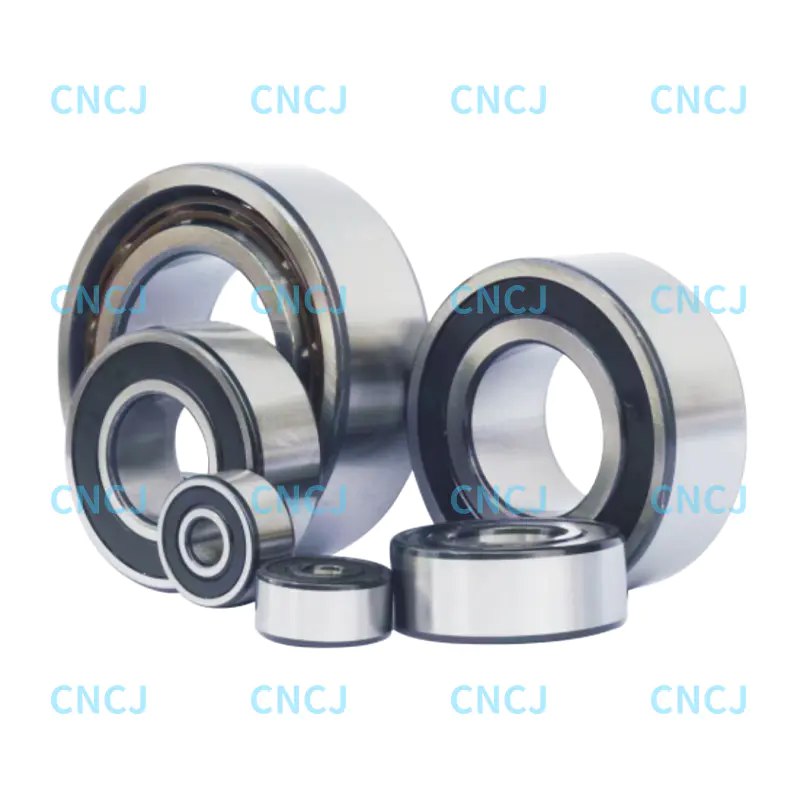
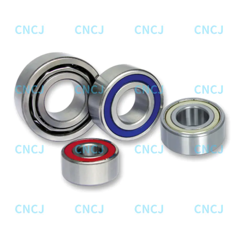
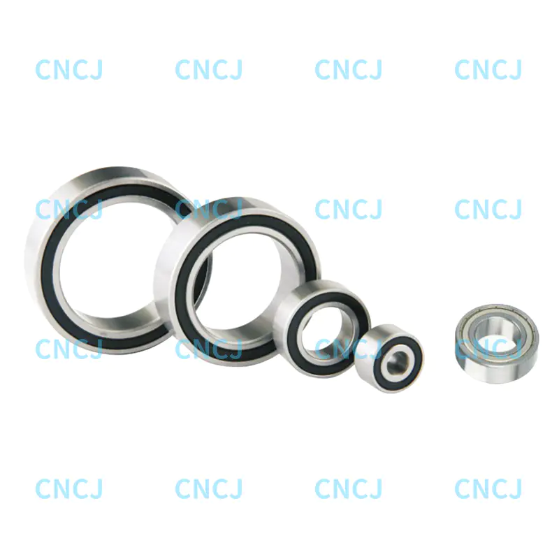
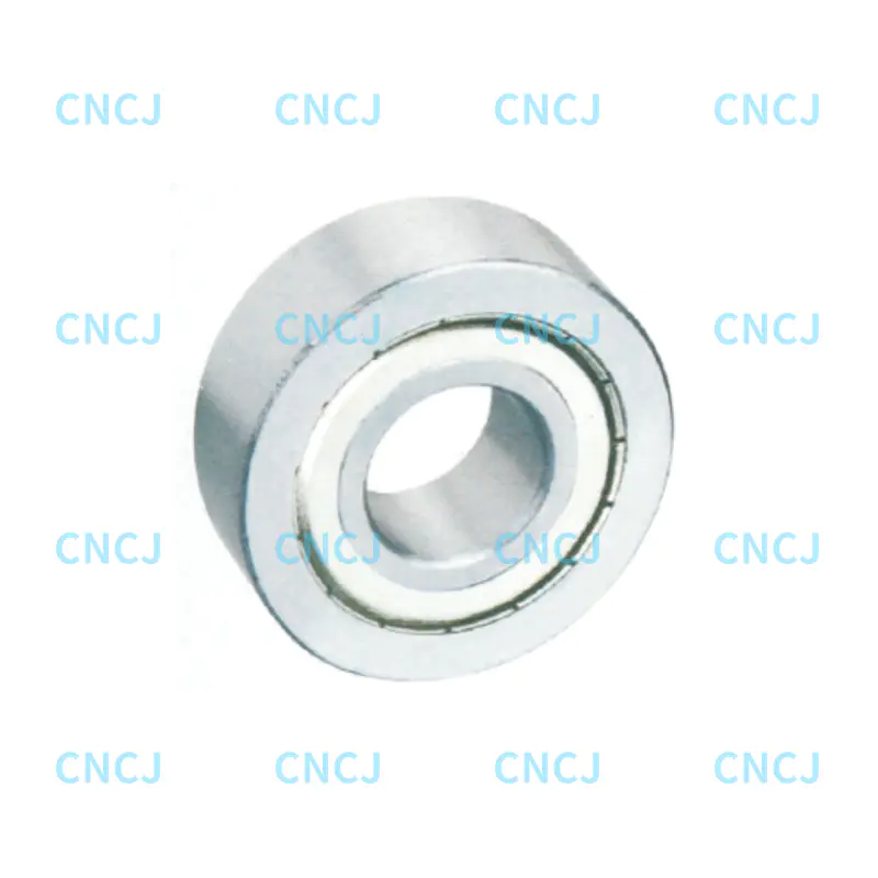
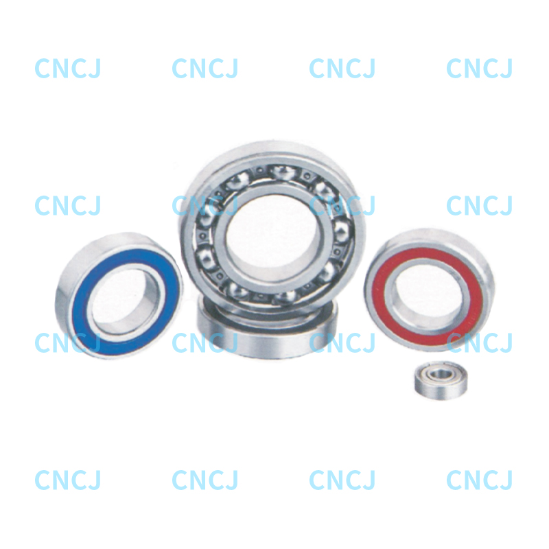 Deep Groove Ball Bearings for Precision Rotating EquipmentReview deep groove ball bearings for fit calculations in motors, automobiles, agricultural machinery, and machine tools, with inquiry and related series links.View Product →
A k5 shaft at 25 mm measures +2 to +11 microns. Against a bore of 0 to minus 10 microns, the joint lands between 2 and 21 microns of interference, which is a light and dependable press fit for a rotating inner ring under normal load. The housing side behaves differently: an H7 bore usually leaves a small clearance, and that clearance is intentional, since a non-locating outer ring must be free to creep slightly as the shaft grows with heat.
Ring fits also interact with bearing geometry in a way a plain hub never does. On a solid steel shaft, an interference fit shrinks internal clearance by roughly 70 to 80 percent of the interference value, so a 20 micron fit removes about 15 microns of clearance. This is why a bearing that turns freely on the bench can feel tight once seated, and why the topic of internal clearance and preload belongs next to the fit chart on any engineering desk.
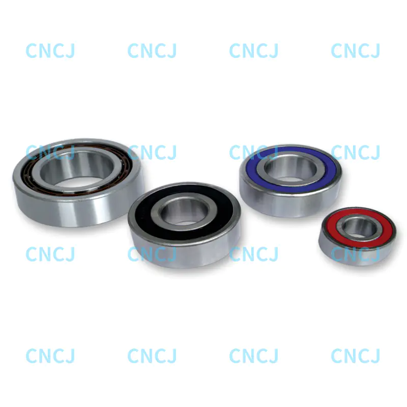 32 and 33 Series Double Row Angular Contact Ball BearingsHigh-rigidity 32 and 33 series bearings handle radial and axial loads in machine tools and gearboxes; confirm shaft and housing fits to avoid preload.View Product →
Double row angular contact designs react the same way, and the effect compounds when two rows share the same ring. A tight fit that was acceptable for a single row can push a double row unit into preload and raise running temperature, so the shaft and housing tolerances should be confirmed before the bearing is ordered rather than after the first test run.
Common Press Fit Problems and Their Causes
- Galling and scoring during pressing, usually from surface roughness, insufficient lubricant or a missing lead chamfer.
- Plating surprises. Hard chrome or nickel adds roughly 5 to 20 microns per surface, so a shaft that was inside tolerance before plating turns a press fit into a jam.
- Lost interference in service, caused by differential thermal expansion, creep and local yielding, with aluminium hubs as the usual victims.
- Measurement error. A micrometer or bore gauge calibrated at 20 C reads a part measured at 30 C about 3 microns small on a 25 mm steel shaft, which is enough to flip a marginal fit.
Specifying and Inspecting the Fit on the Shop Floor
Write both the class and the expected result on the drawing: an H7/p6 note plus the calculated interference range of 1 to 35 microns leaves nothing to interpretation. Where the joint is safety related, add a note that the push-out force of a sample assembly must be verified.
Inspection should happen at a stable temperature, using a micrometer on the shaft and an air gauge or bore gauge on the housing, with roundness checked at two planes. Lubricate before pressing, keep the press stroke slow and square, and treat a joint that has already been pressed twice as a weakened joint rather than a reusable one.
Press Fit Tolerance Chart Questions
What tolerance is used for a press fit?
There is no single value. At 25 mm nominal size, H7/p6 gives 1 to 35 microns of interference and H7/s6 gives 14 to 48 microns. Bearing bores follow their own class tolerances, so those joints are calculated separately.
How much interference is needed?
Enough to carry the torque by friction, plus margin for temperature and roundness losses. Light machinery commonly uses 5 to 20 microns at 25 mm, while heavy industrial joints often run above 30 microns.
Why does a press fit fail even when the chart was followed?
Because the chart describes ideal round, clean parts at 20 C. Plating thickness, ovality, thermal growth and repeated assembly are the usual reasons a correct chart value still produces a loose or seized joint.
Treat the press fit tolerance chart as the start of a decision rather than the decision itself. Pick the size band, read the interference range, subtract what temperature, surface condition and wall thickness will take away, and only then commit the fit to the drawing. In rotating equipment, the ring fit and the internal clearance have to be chosen together, because that pairing decides whether a machine runs quietly for years or returns to the workshop for rework.
 English
 中文简体
 Deutsch
 Español