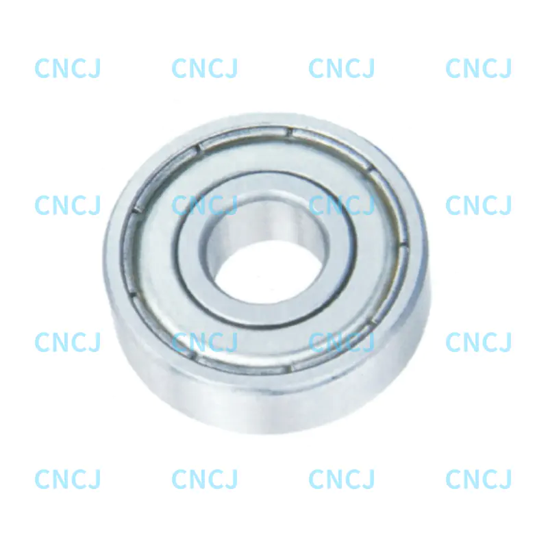
A 25 mm shaft that measures 24.990 mm, dropped into a housing bore that measures 25.020 mm, leaves a gap of 0.030 mm. Nothing looks wrong on the drawing, both parts pass a quick caliper check, and yet that gap decides whether the assembly runs quietly or shakes itself loose after a month of production. Shaft and hole tolerance is what sets that gap or that grip, and it is usually the first thing worth re-checking when a rebuild fails twice in the same way.
The practical answer is short. Work in a hole basis system such as H7 unless there is a clear reason not to, choose the fit class from the load direction, the temperature difference and the assembly method, then confirm the result in thousandths of a millimetre instead of assuming the machinist will land exactly on nominal.
How a Shaft and Hole Tolerance Is Written
A size such as 25 H7 carries two separate pieces of information. The letter H fixes the position of the tolerance zone relative to nominal 25 mm. For a hole, upper case H means the lower limit sits exactly at nominal, so the zone runs upward from 25.000 mm. The number 7 fixes the width of that zone, which is called the tolerance grade. At 25 mm, IT7 equals 0.021 mm, so an H7 hole may measure anywhere between 25.000 mm and 25.021 mm.
A shaft written as 25 h6 follows the same logic in the opposite direction. Lower case h puts the upper limit at nominal, so the shaft runs from 24.987 mm to 25.000 mm. Changing the letter moves the whole zone. Changing the number only changes how wide the zone is, and that width grows quickly with nominal size.
Tolerance grade widths for nominal sizes above 18 mm and up to 30 mm, all values in millimetres, based on ISO 286.
| Tolerance grade |
Zone width at 25 mm |
Typical use |
| IT6 |
0.013 mm |
Precision fits, bearing seats, fine machine spindles |
| IT7 |
0.021 mm |
Standard hole basis fits, general machinery housings |
| IT8 |
0.033 mm |
Pressing and locating fits with moderate load |
| IT9 |
0.052 mm |
Loose running fits, covers on non critical joints |
| IT10 to IT11 |
0.084 to 0.130 mm |
Welded or bolted structures, generous clearances |
The step from IT7 to IT9 more than doubles the allowed band. That single grade often separates a controlled press fit from an assembly that needs retaining compound to stay together.
Hole Basis or Shaft Basis
ISO 286 lets you anchor the tolerance zone on either part. In a hole basis system the hole stays at H and the shaft letter changes to create the fit. In a shaft basis system the shaft stays at h and the hole letter changes.
Hole basis wins in most production because holes are harder to finish to size and easier to gauge. A reamer, a boring bar setting or a plug gauge is dedicated to one nominal diameter, so keeping the variation on the shaft, which is turned and ground to whatever size is needed, holds tooling costs down. Shaft basis makes sense when one finished shaft, such as a ground spindle or a cold drawn bar, must accept several different hubs, or when one shaft length is shared across a product family.
Clearance, Transition and Interference Fits
Once both zones are known, the fit is the difference between them. The result is a gap, a range that crosses zero, or a permanent grip. The table below shows the same 25 mm joint with five shaft letters against an H7 hole. Negative values mean interference.
Clearance and interference ranges for a 25 mm H7 hole paired with common shaft tolerances, values in millimetres.
| Fit |
Type |
Clearance range |
Where it fits |
| 25 H7/h6 |
Clearance |
0.000 to +0.034 mm |
Locating with light movement, assembly by hand |
| 25 H7/g6 |
Clearance |
+0.007 to +0.041 mm |
Close sliding with an oil film, spindles and guides |
| 25 H7/k6 |
Transition |
-0.015 to +0.019 mm |
Location fits where keys or dowels carry the torque |
| 25 H7/p6 |
Interference |
-0.035 to -0.001 mm |
Light press, retains a bush without fasteners |
| 25 H7/s6 |
Interference |
-0.048 to -0.014 mm |
Permanent force fit, press or shrink assembly |
Notice that H7/k6 crosses zero. Any transition fit is a bet on the sizes actually produced, so it is reliable only when both parts are measured or made under statistical control. Across a batch of fifty bushes, a transition fit usually delivers a few tight parts and a few loose ones.
Why Bearing Seats Do Not Follow IT Grades
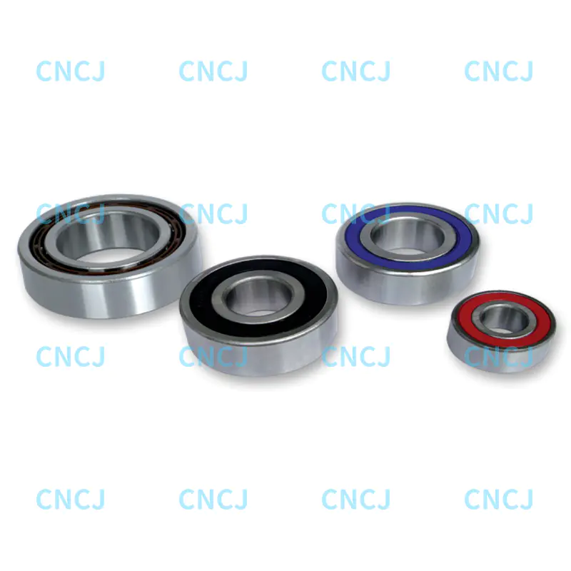
Rolling bearings arrive finished, so their bore and outside diameter are toleranced by the bearing standard rather than by ISO 286. For a 25 mm bore in the normal tolerance class, the bore is nominal or up to roughly 0.010 mm smaller, and it never runs oversize. That single rule changes how the mating shaft must be written, because a shaft produced at exactly 25.000 mm is already a light interference in that bore.
Thin section rings add a second complication. A pressed ring takes the geometry of its seat, so a housing that passes the diameter check but carries 0.010 mm of ovality transfers that shape straight into the raceway. On high precision assemblies, roundness and taper usually matter more than the diameter band itself.
The working rule is that the ring rotating relative to the load direction needs the tighter seat, while the stationary ring can run looser. In a fan with a rotating shaft and a fixed housing, that means a shaft seat around k6 or m6 and a housing around H7 or J7. Reverse the arrangement and the housing becomes the tight side.
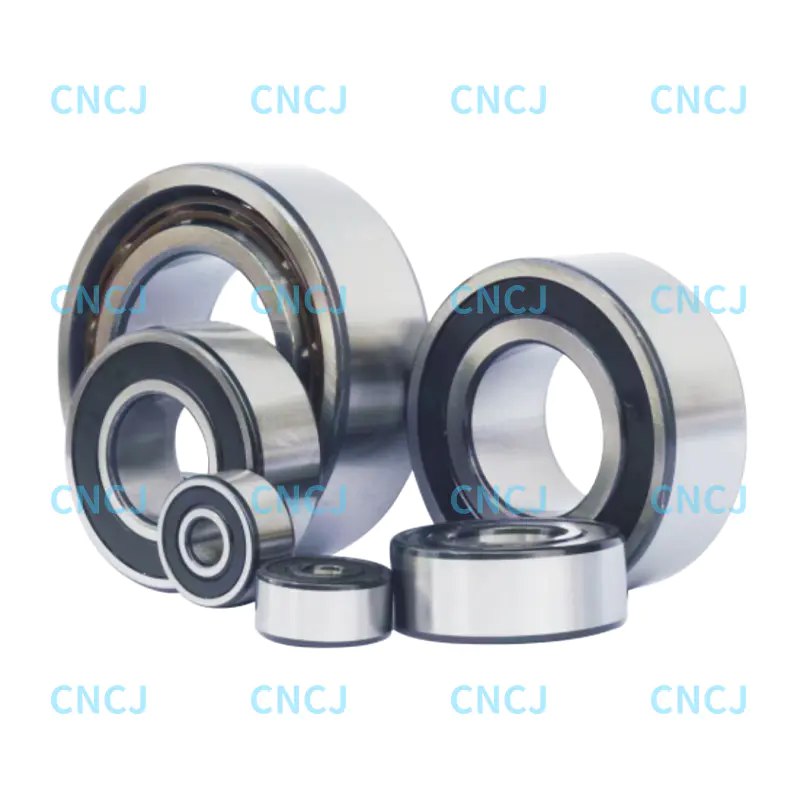
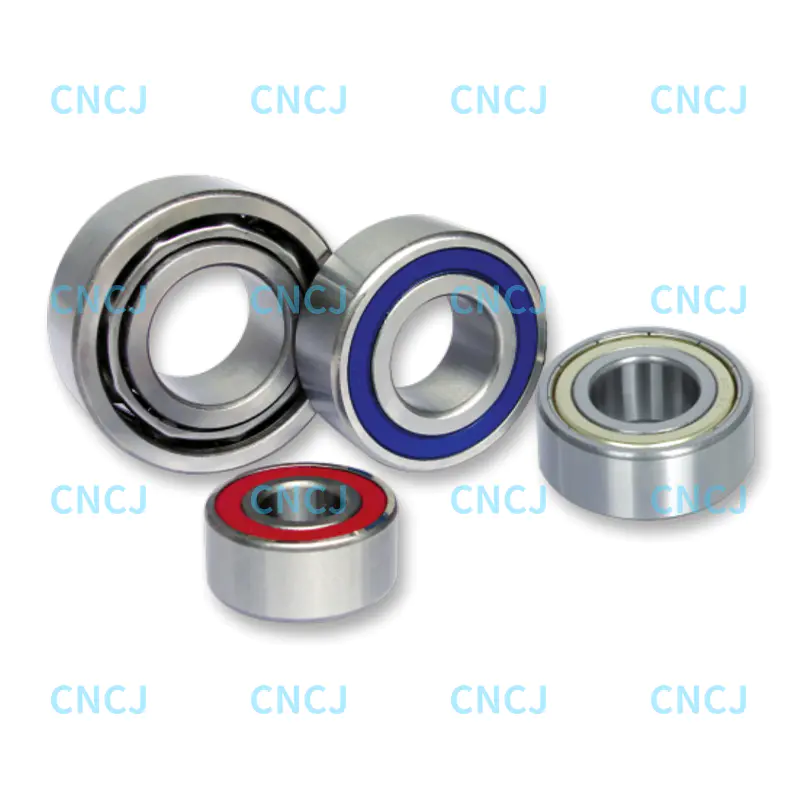 52 and 53 Series Double Row Angular Contact BearingsUseful where fit class and preload must be balanced, these double-row angular contact bearings carry combined loads with sealed designs and low-friction lubrication.View Product →
Fits also interact with internal clearance. A double row angular contact bearing seated with a press fit on both rings loses part of its running clearance to the elastic squeeze, which is one reason preload and fit class have to be chosen together. Our note on selecting preload for 52 and 53 series bearings walks through the same trade-off from the bearing side.
Things That Override the Drawing
Temperature
Steel grows about 0.0115 mm per 100 mm of length for every 100 degrees Celsius of temperature rise. On a 25 mm shaft that is roughly 0.029 mm, wider than an entire IT7 band. A hot shaft slides into a cold housing far more easily than the drawing suggests, and a joint that felt right on a cold bench can lose its grip once the machine reaches working temperature.
Roundness and taper
A three lobed bore can report a perfect diameter when measured across two points while behaving like an interference fit in service. Check roundness at three positions and keep taper inside a bearing seat to a fraction of the diameter tolerance.
Surface finish and coating
Interference is measured across the peaks of two surfaces. Grinding marks and turning peaks flatten during pressing, so a rough shaft loses roughly one to two thousandths of a millimetre of effective grip. Plating and paint on a housing bore move the other way and must be added to the nominal size before the fit is calculated.
Measurement conditions
Limits and fits assume 20 degrees Celsius and a calibrated instrument. A micrometer held on a hot part, a caliper squeezed with heavy thumb pressure, or a shop floor that swings twenty degrees between shifts can all scrap a perfectly good component.
Assembly method
A joint that needs ten tonnes of press force on paper may need a hydraulic press, an induction heater or a shrink fit in practice. If the only tooling available is a dead blow hammer, reduce the interference before production starts rather than after the first cracked housing.
How to Specify a Fit Without Rework
- Fix the nominal size from the functional requirement, not from the nearest stock bar.
- Decide the load direction for each part and identify which component rotates relative to the load.
- Choose the fit type first: clearance for movement, transition for location, interference for a permanent grip.
- Adopt the hole basis and write the hole as H plus the grade that matches the required accuracy, usually H7 or H8.
- Select the shaft letter that produces the clearance or interference you want, then write out both limits in millimetres.
- Check the numbers against temperature, coating thickness and available assembly tooling before releasing the drawing.
- State the measurement method and temperature on the drawing whenever the band is tight.
Writing both limits explicitly is the step most often skipped, and it is the one that saves the most money, because it removes any argument about what H7 means for that particular diameter.
Where These Choices Show Up in Real Equipment
General rotating support, from pumps and fans to small gearboxes, usually runs a deep groove ball bearing on a shaft seat in the j5 to k6 range and a housing in H7 or J7, with the tighter side placed on whichever ring carries the rotating load.
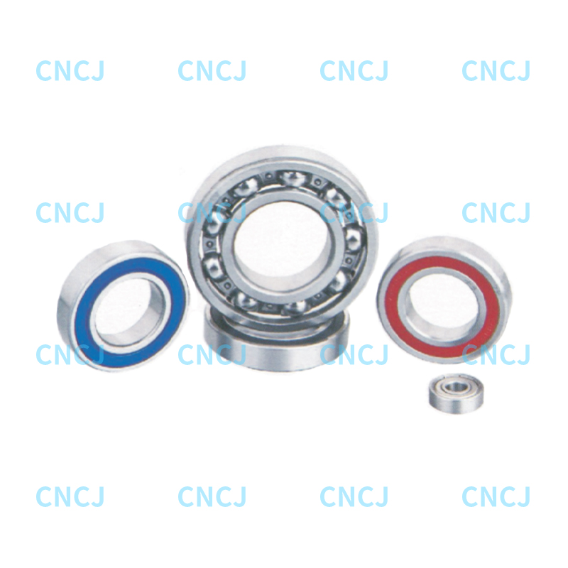 Deep Groove Ball Bearings for General Rotating SupportSimple, high-load-capacity, low-friction bearings for pumps, fans and gearboxes, with 42 and 43 series in multiple specifications.View Product →
Equipment that must stay stable under combined radial and axial load, such as compact drives, conveyor rollers and guided vehicles, often uses a double row bearing with both rings seated more firmly. Here the fit and the internal clearance have to be tuned together, because too much squeeze on both rings removes the running clearance that keeps noise and vibration low.
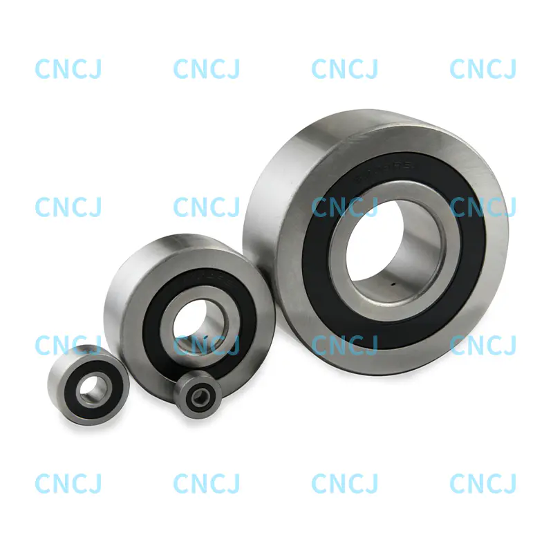
Double Row Ball Bearings for Combined Radial and Axial LoadsDouble-row angular contact bearings take radial and two-direction axial loads, add high rigidity, and suit hubs, precision machinery, and firmly seated arrangements.View Product →
At Ningbo Wanshun Bearing, the tolerance questions we receive from machine builders almost always involve a seat copied from an older drawing without rechecking the load direction or the operating temperature.
Keeping Tolerance Decisions Simple
Shaft and hole tolerance is a small piece of arithmetic with a large effect on reliability. Anchor the zone on the hole, choose the fit type from the job the joint has to do, and write both limits so the shop, the inspector and the buyer read the same numbers. When a joint has to work hot, sit on a thin ring bearing, or carry heavy load, treat the fit and the internal clearance as one decision rather than two, because in service they behave that way.
 English
 中文简体
 Deutsch
 Español