An engineer on a motor repair line measures a freshly bored housing at 25.033 mm. The drawing calls for H8, so the size is legal, but the fit will only work if the shaft tolerance and the bearing choice match. H8 is one of the most common hole tolerance classes in ISO 286, and it is also one of the most frequently misread. In plain terms, H8 means the hole may sit anywhere from nominal size up to a defined oversized limit, with no undersized deviation. For a 25 mm bore, that window is 0.033 mm wide. This article explains what H8 actually controls, how it compares with other grades, and how to apply it to bearing seats without guessing.
What H8 Tolerance Means in ISO 286
ISO 286 defines tolerance classes as a combination of a fundamental deviation, shown by a letter, and an international tolerance grade, shown by a number. The letter H marks a hole whose lower deviation is zero, so the smallest acceptable diameter equals the basic size. The number 8 refers to the IT8 grade, which sets the width of the tolerance zone. H8 therefore allows a hole that is exactly nominal at the low end and up to the IT8 limit at the high end.
Because the restriction applies only on the upper side, H8 is unilateral. A 25 mm H8 bore measures anywhere from 25.000 mm to 25.033 mm. This behaviour is convenient in machining: the cutter starts at nominal size and may wear outward, and the part stays acceptable until the bore passes the upper limit. Inspection is also simple, because the lower limit is always the nominal dimension.
Hole Basis versus Shaft Basis
ISO 286 supports both a hole basis and a shaft basis system. H8 is a hole basis class, so the hole is held to a fixed deviation while the shaft is selected to create the desired fit. This approach is usually cheaper because standard reamers, boring tools, and plug gauges are built around the H series. Shaft basis fits are still common in the bearing industry for outer ring seats, but general machining drawings most often start from an H6, H7, or H8 hole.
H8 Tolerance Values across Basic Size Ranges
The width of the H8 zone is not constant in absolute terms. It grows as the basic size grows, because production at larger diameters naturally accumulates more dimensional variation. Table 1 lists the limit deviations for H8 bores in millimetres over the ranges most relevant to bearing mountings.
Table 1: H8 hole limit deviations per ISO 286 for common basic size ranges.
Basic size range (mm)
Lower deviation (mm)
Upper deviation (mm)
Over 0 to 3
0
+0.014
Over 3 to 6
0
+0.018
Over 6 to 10
0
+0.022
Over 10 to 18
0
+0.027
Over 18 to 30
0
+0.033
Over 30 to 50
0
+0.039
Over 50 to 80
0
+0.046
Over 80 to 120
0
+0.054
Chart 1 visualizes how the upper limit rises with the size range. The bars show the maximum permitted oversize of an H8 bore for each range. When comparing drawings of different shaft sizes, this trend matters more than most people expect.
Chart 1 compares the H8 upper deviations across eight basic size ranges from 0 to 120 mm. Each bar shows the maximum amount by which the bore may exceed its nominal size. The pattern is smooth and steadily increasing, from 0.014 mm at the smallest range to 0.054 mm at the 80 to 120 mm range. A designer who sees the same H8 symbol on two drawings of different diameters should not assume the same maximum oversize. A machining shop should not use one single cutoff value as the acceptance limit for all H8 bores. The inspection gauge must be matched to the actual diameter under consideration.
How H8 Compares with H7, H9 and H11
Selecting a tolerance grade is a trade between functional precision and manufacturing cost. H7 is the default for many precision bearing seats and sliding parts. H8 relaxes the zone by roughly half as much again and is common for housing bores, pulley seats, and general clearance fits. H9 and H11 widen the zone much further and appear only when alignment is not critical.
For a 30 to 50 mm hole, the upper limits are 0.025 mm for H7, 0.039 mm for H8, 0.062 mm for H9, and 0.160 mm for H11. The jump from H8 to H11 is more than four times wider, which changes the behaviour of the fit dramatically. Chart 2 shows how the tolerance zone grows across diameter ranges for these four grades.
Chart 2 plots the upper deviation of four common hole tolerance grades against the basic size range. Each line rises from left to right, confirming that the tolerance zone expands with diameter. The distance between the H7 and H8 lines stays modest, which is why both grades are used for similar applications. The gap between H8 and H9 is much larger, and the H11 line sits far above the rest. This visual comparison makes it clear why switching from H8 to H9 or H11 without redesigning the fit can lead to visible radial play and vibration in a bearing assembly. An H8 machining target is intentionally more precise than a general H9 hole but still more economical than H7.
H8 in Bearing Housing Fits: Clearance Examples
The most common use of an H8 bore is as a housing or pulley seat through which a shaft passes with a running clearance fit. The resulting fit is described by pairing the H8 hole with a shaft tolerance class. Two typical partners are f7 and g6, and the fit follows from their limit deviations.
Table 2: Calculated clearance for H8 bores paired with common shaft tolerances at 18 to 30 mm basic size.
Fit pair
Shaft deviations (mm)
Minimum clearance (mm)
Maximum clearance (mm)
H8/f7
-0.020 to -0.041
0.020
0.074
H8/g6
-0.007 to -0.020
0.007
0.053
H8/h8
0 to -0.033
0
0.066
The fit calculation is simple: subtract the shaft upper deviation and lower deviation from the H8 upper limit to obtain the minimum and maximum clearance. Chart 3 shows these clearance ranges side by side. The taller the pair of columns, the wider the range a designer must accept.
Chart 3 compares the minimum and maximum clearance for three common fits that use an H8 hole at the 18 to 30 mm basic size. The H8/f7 pair gives the widest range, from 0.020 mm to 0.074 mm, which suits shafts rotating at moderate speed in lubricated housings. The H8/g6 pair is tighter, with a minimum clearance of only 0.007 mm, making it suitable for quieter spindles and lower vibration requirements. The H8/h8 pair allows a clearance down to zero, which is useful for sliding assemblies but risky if thermal expansion pushes the parts together. The vertical distance between the minimum and maximum bars shows how much variation the designer must manage. If the application cannot tolerate that spread, H8 may need to be replaced by a tighter class such as H7 or the shaft partner changed.
Inspecting and Buying Parts with H8 Bores
An H8 bore is verified with a two-sided go and no-go plug gauge, a bore micrometer, or a coordinate measuring machine. A go gauge sized to the lower limit, equal to nominal size, must pass. A no-go gauge sized to the upper limit must not pass. The inspection temperature should be close to 20 degrees Celsius, because a machined aluminium housing can move tens of microns with only a few degrees of temperature change.
Several practical issues hide behind a simple H8 callout:
Roundness errors are not covered by a size check, so an oval bore can measure within H8 yet still create uneven wear or premature seal failure.
Surface finish matters because a rough-walled H8 bore reduces effective clearance and accelerates fretting under vibration.
When buying machined parts, ask for the actual measured bore values rather than a certificate that simply states H8.
Separate the design intent from the bearing manufacturer recommended seat tolerance. Many deep groove ball bearings mount acceptably in H7 or H8 housings depending on load and speed, but the outer ring must not be free enough to rotate in the housing. If you plan to assemble a bearing into an H8 bore, verify that the effective fit still meets the operating requirements.
Choosing the Right Bearing for an H8 Housing Bore
An H8 housing is often used with deep groove ball bearings in electric motors, gearboxes, conveyors, and light machinery where the outer ring stays stationary in the seat. If the housing bore sits near the upper H8 limit, the outer ring will be noticeably freer, so noise and vibration should be checked early in the test run. On many production lines, an upper limit H8 bore still works, but the radial internal clearance of the bearing and the shaft tolerance must be matched to the actual duty.
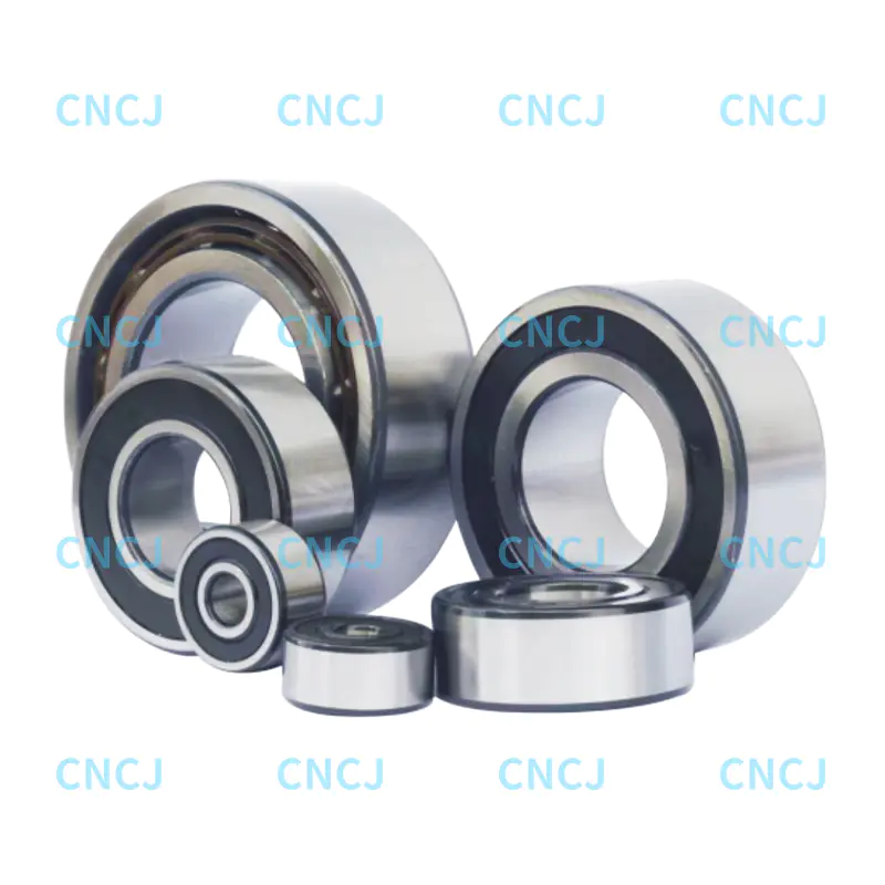
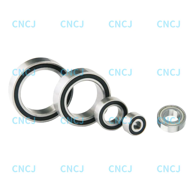
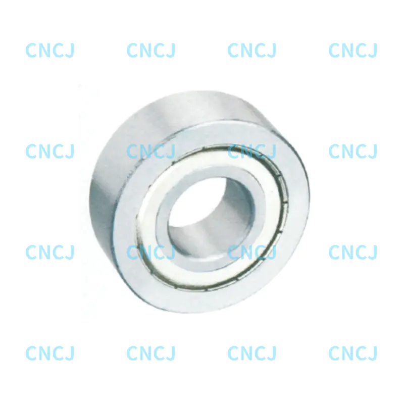
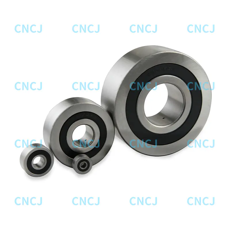
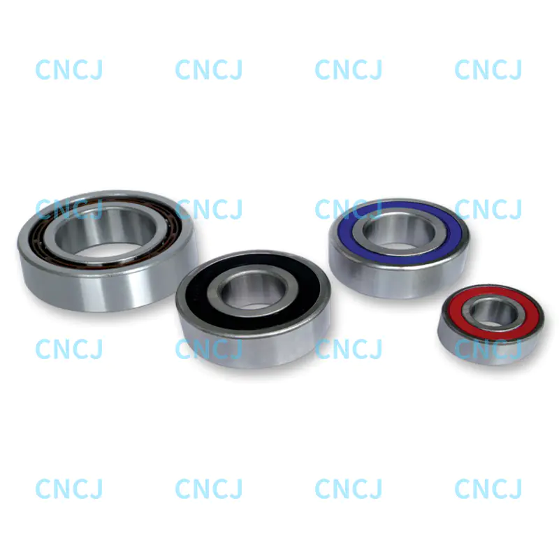
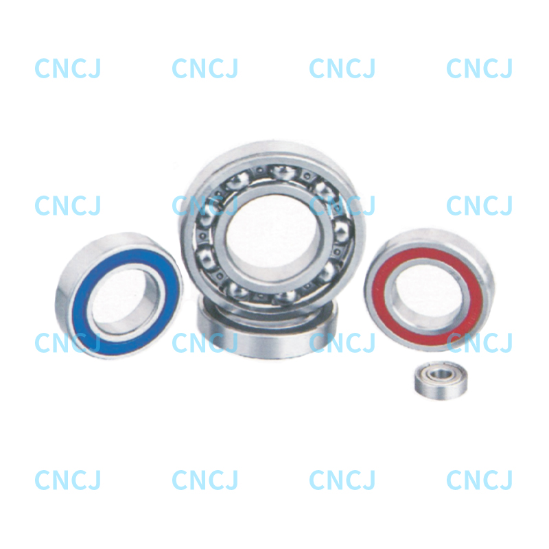
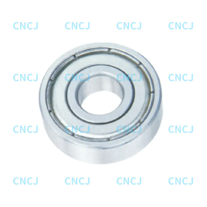
For a straightforward replacement or a new medium speed design, deep groove ball bearings cover most housing bore applications from 3 to 200 mm bore size. They handle moderate radial loads, run quietly, and are a practical first choice when the H8 seat is already machined.
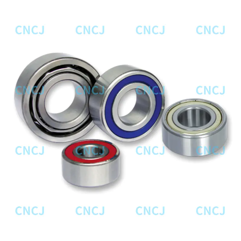
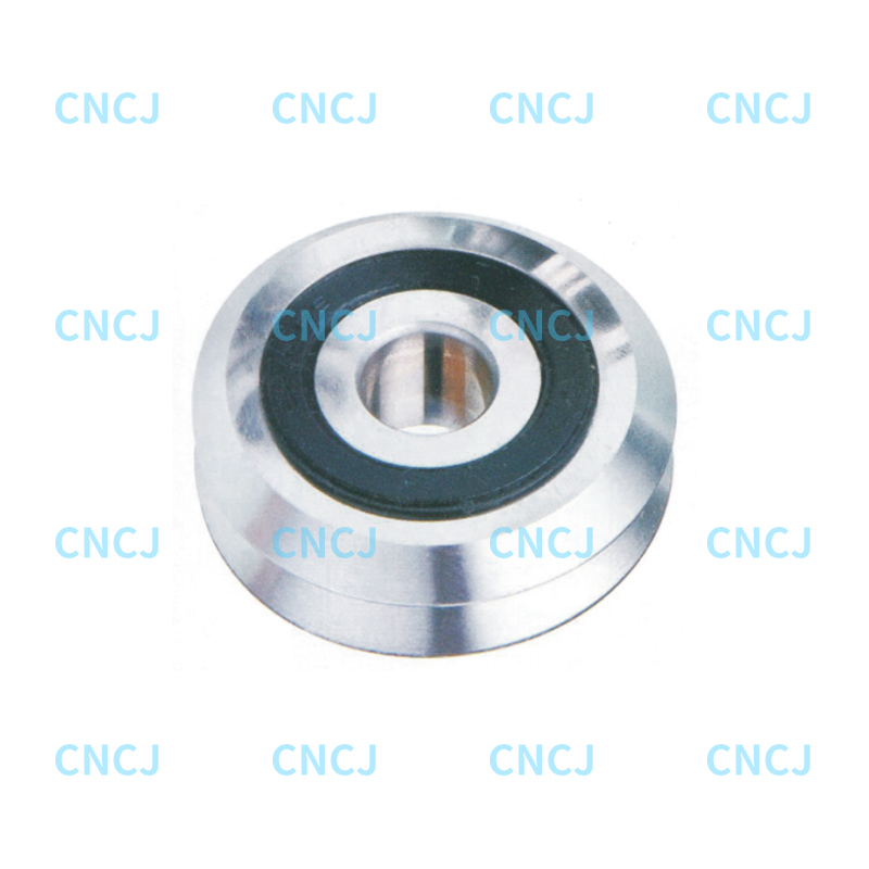
For applications with higher combined radial and axial loads, a double row angular contact ball bearing offers better rigidity in the same housing arrangement. The contact angle and preload change how the bearing reacts to an H8 seat, especially under moment loads. Where the shaft must carry heavier loads in a compact envelope, double row angular contact ball bearings give a stronger solution while still allowing a standard housing tolerance.
Whatever the bearing type, bearing installation procedures become more critical when the housing bore sits close to the upper H8 limit, because a loose outer ring can spin and generate heat. A practical approach is to specify a slightly tighter housing for heavy or high speed duty, then relax the tolerance only after test data shows that temperature and noise are stable.
Choosing H8 is only the first step. The tolerance class fixes the size window, but actual performance still depends on the shaft partner, the bearing type, surface finish, temperature, and measurement method. Verify the bore at both ends and in two planes, confirm the effective clearance with the chosen bearing, and compare the supplier machining data before assembly. A small investment in metrology at the prototype stage prevents large field failures later. When in doubt, start from a proven combination such as H8 with f7 or g6, and tighten the grade only when the duty cycle justifies it.
 English
 中文简体
中文简体 Deutsch
 Español